Device real-time

By accessing real time whilst in the programming section of a module, the software opens the following section:
|
|
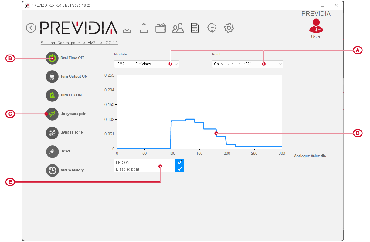
This section shows a graph containing the values read by the device (in accordance with its type) during the monitoring period (seconds):
- Level of smoke in the protected environment in mdB/m (for optical detectors)
- Temperature in the protected environment in °C (for heat detectors)
- Input resistance in Ohm (for modules)
In the case of optical-heat detectors the graph shows both the level of smoke (in light blue, on the left) and the temperature (in red, on the right).
The available functions depend on the type of device being monitored:
|
Turn On output |
|
Button to switch ON/OFF the device output. |
|
Turn On LED |
|
Button to switch ON/OFF the device status LED. |
|
Bypass point |
|
Button to bypass the device |
|
Bypass zone |
|
Button to bypass the entire zone to which the device belongs |
|
Reset |
|
Button to refresh the displayed window |
|
Alarm history |
|
Button to start a procedure with the purpose of displaying graphs showing the trend over time of the values detected by the device in the 5 minutes before the last alarm. |